
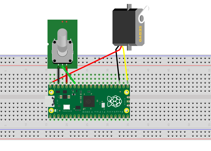
在上面的电路图中:
- 伺服电机红线连接到 Pico Vbus 引脚(5V)
- 伺服电机棕色线连接到 Pico GND
- 伺服电机黄线连接到 Pico PWM 引脚(GP16)
- 电位器 GND 连接到 Pico GND
- 电位器 VCC 连接到 Pico 3.3V
- 电位器中间引脚连接到 Pico ADC 引脚(GP28)
代码: 全选
from machine import Pin, PWM,ADC #import libraries for Pin, PWM, ADC
from time import sleep

adc = ADC(Pin(28)) #set Potentiometer analog input from GP28 pin

servoPin = PWM(Pin(16)) #set servo pwm output to GP16 pin
servoPin.freq(50) #set servo frequency 50

def servo(degrees): #rotate servo arm to degrees position
# limit degrees beteen 0 and 180
if degrees > 180: degrees=180
if degrees < 0: degrees=0
# set max and min duty
maxDuty=9000
minDuty=1000
# new duty is between min and max duty in proportion to its value
newDuty=minDuty+(maxDuty-minDuty)*(degrees/180)
# servo PWM value is set
servoPin.duty_u16(int(newDuty))

while True:
value=adc.read_u16() #read Potentiometer value
print(value)
degree=value*180/65500 #convert Potentiometer value to a servo position angle
servo(degree). #rotate servo to that angle
sleep(0.001)